- Pilotage
- Visual navigation relying on maps/ landmarks such as rivers, roads, cities, others
- Preflight planning for pilotage begins with obtaining a correct and current chart
- Arrange chart so that you can easily see the whole route
- Decide the areas you would like to avoid (airspace's, mountains, etc)
- Use a plotter to measure the length of your course in NM, and use a pencil to mark the course
- Select checkpoints in between departure and destination, you want to always know your location
- Dead reckoning
- Navigation based on calculations on time, speed, distance, and direction
- The compass provides the necessary directional info
- Course direction is measured with a plotter
- Draw your course on the chart as you would for a pilotage flight, including distance, fuel, other
- Flight planning
- Do as much as possible on the ground
- Make checkpoints
- Determine the effects of wind
- Right down all frequencies you may need
- VFR cruising altitudes
- Many factors help decide your altitude
- Height above terrain and obstruction
- The higher you are the more time you have to find an emergency landing spot
- When in level cruising flight at 3000 feet above the surface, you must comply with VFR cruising altitudes rule
- VFR aircraft's on heading from 0º to 179º are required to fly at odd thousand-foot altitudes + 500 feet
- VFR aircraft's on heading from 180º to 369º, you must fly evens + 500 feet
- If you are maneuvering, turning, or changing altitude, the rule does not apply
- The reason for this is traffic separation
- Flight plan
- When you file a flight plan with FSS, a record is made that provides your flight info
- Flight plan will be kept on file for 1 hour
- Once airborne, you activate your flight plan so FSS can keep track of your ETA
- If you do not close or extend your flight plan within 30 minutes after your stated ETA, the FSS will begin a preliminary search by telephone, then notify search and rescue organizations
- Flight plan should include provisions to start a search and rescue if you fail to arrive
- Use VFR flight plan service provided by the FSS
- Lost procedures
- 5 C’s
- Climb
- Usually helps you see more of the ground
- Improves reception range of your radio and navigation equipment
- Communicate
- Available facilities
- Confess
- To ATC
- Comply
- ATC instructions
- Conserve
- fuel

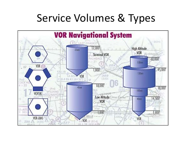
VOR navigation
- How they work
- Very high frequency omnidirectional range
- Sends out two different signals. One master and one secondary
- Master signal is constant for each radial
- Secondary signal rotated about the station
- Receiver compares the two signals and can tell you where the selected radial is
- Limited to line of sight
- Station and radials
- 360º
- Radials are always from the station
- Oriented to magnetic north
- VOR roughness
- Minor CDI roughness brief flag alarm if flying over mountainous terrain
- Standard service volumes
- HSI
- Combines vor and directional gyro
- Also gives you glide slope
- VOR navigation
- Station ID
- Find the Morse code on sectional or low en-route chart
- Press ID button -> turn up volume -> listen to Morse code
- During maintenance Morse code removed or send out test signal ( _••••_ )
- Intercepting radial
- Take the difference between the radial you are on and the radial you want to intercept
- On radial 100 and want to intercept radial 120 -> 20º difference
- Radial difference * 2 ( not less than 20º and not more than 90º intercept angle)
- If flying to the station, always set course to reciprocal radial
- Turn into the course
- Tracking
- Follow the selected radial
- If the CDI goes to the left, turn to the left
- Remember to correct for wind drift
- Homing
- Continuously twist the obs knob to center the CDI
- Reverse sensing
- When the CDI indicates the reverse of normal operations
- This will happen to a basic VOR if you set it to the reciprocal of the intended course
- Station passage
- The CDI will be more sensitive the closer you get to the station
- Eventually oscillations and/ or full scale deflection
- Cone of confusion
- Nav flag may also appear
- Station passage is complete with flag flip (to/from)
- 1 NM from VOR maintain heading
VOR CHECKS
- Has to be done every 30 days
- VOT - VOR test facility
- Transmits a test signal which can be found in the A/fd
- Procedure
- Tune in frequency in VOR receiver
- Center the CDI needle
- Should read 180º with a TO indications or 0º with FROM (think blink 182
- Maximum error is +/- 4º
- VOR receiver checkpoint
- Frequency and radial can be found in A/fd
- Procedure
- Tune in frequency in VOR receiver
- Center CDI needle
- Should read radial specified in A/fd with a from indication
- Max error +/- 4º for ground check
- Maximum error +/- 6º for airborne check
- Dual VOR check
- Used for 2 VOR independent from each other
- Maximum error is 4º between 2 receivers
- VOR records
- Each person making the check must enter the info in the aircraft or other records(91.171)
- “D.P.E.S” date, place, error, signature
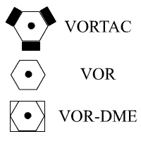
- VOR, VOR DME, AND VORTAC
- VOR provides course information
- VOR.DME provides course and distance
- VORTAC is both VOR and tacan
- TACAN is used by military - provides course and distance
DME navigation
- Distance measuring equipment
- Works on line of site
- Aircraft has a DME transmitter that send out radio frequency pulses
- A ground facility receives the signals and sends them back to the aircraft
- The airborne DME measures time between the signal and translates it into distance
- Reliable signal will be received up to 199 NM line of site
- Slant range
- Distance is measured from your aircraft to the station, not ground distance
- The error is greater the higher you are and the closer you are to the station
- Frequency pairing plan
- You only have to put in the VOR frequency to receive the distance info
- This assumes that the station has DME info (VOR/DME, VORTAC, ILS/DME,LOC/DME)
- DME is identified by a morse code with a tone slightly higher than the VOR/LOC tone
- Heard once every 3 - 4 times the VOR/LOC

NDB navigation
- Ground facility
- Called NDB - non directional radio beacon
- Transmits radio energy in all directions
- Frequencies
- Not approved for IFR navigation but can be used for VFR
- ADF receivers do not have a "flag" to warn the pilot when erroneous bearing information is being displayed
- The pilot should continuously monitor the NDB's identification
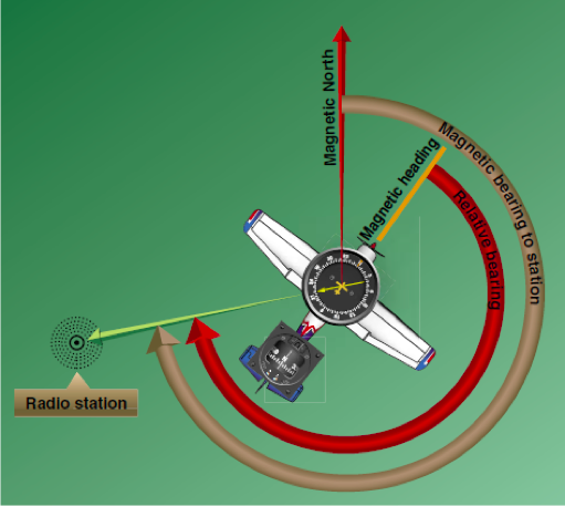
- ADF - automatic direction finder
- Equipment in the aircraft
- Always points to the antenna
- Shows you the relative bearing from the aircraft's magnetic heading to the transmitting station
- Can be a fixed card or a moveable card bearing indicator
- MH + RB = MB
- RMI - radio magnetic indicator
- ADF’s version of the HSI
- Combines and ADF with a heading indicator connected to a fluxgate
- MH + RB = MB

No comments:
Post a Comment