Ground Lesson 25(13): Approach charts
Approach segments
- Feeder routes
- en route structure to the initial approach fix
- Initial approach segment
- This segment starts at the IAF - initial approach fix
- The purpose is to align your aircraft with the approach course
- Can be DME arc, procedure turn, or holding pattern
- Intermediate approach segment
- Starts at the IF - intermediate fix
- Designed to position your aircraft for the final descent to the airport
- Reduce your airspeed to the approach speed and complete FAF briefing (TAMALL)
- Some charts don't show IF
- Starts when you intercept the inbound course after completing the procedure turn
- Final approach segment
- Starts at the FAF - final approach fix
- Allows you to navigate safely to the airport
- Can't see the airport environment at the MAP you must execute a missed approach
- If the approach does not have a FAF, it starts when you are established inbound after completing the PT
- Missed approach segment
- Starts at the MAP
- Allows you to navigate to a point where you can try again or continue to another airport
Approach chart layout
- Approach name conventions
- HIO VOR/DME C
- “C” stands for the third circling only approach to that airport
- VOR/DME means you must have both VOR/DME equipment
- BFI RNAV(GPS) Y Runway 13R
- “Y” stands for the second approach of the same type to the same runway
- Starts at “Z” and goes backwards
- BFI also has RNAV(GPS) Z runway 13R
- Heading section
- The “header” of the approach plate
- Gives the name of the approach, airport name, city, and state
- This title is used by ATC when they clear you for the approach
- Briefing information
- What you should brief before starting the approach
- Contains approach course, frequencies, and elevation
- Minimum safe altitude
- Provides 1000 feet obstacle clearance within 25 NM of the indicated facilities
- (same for mountainous and non mountainous )
- Divided into sectors
- Does not guarantee NAV or, COMM coverage
- Designed only for use of an emergency
- Plan view
- Middle section where you see the approach from above
- Missed approach segment shown with dotted line
- Profile view
- Bottom section where you see the approach from the side
- Step-down fix and Visual Descent Points (VDP)
- As you pass certain points you may descend down to a new altitude
- VDP = visual descent point
- A point from which you can make a normal descent to a landing from the MDA
- Missed approach icons
- Conversion table
- Rule of thumb → groundspeed/2 * 10 feet/minute
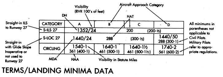
- Landing minimums
- MDA → minimum descent altitude for non precision approaches
- DA → decision altitude for precision approaches
- Provides altitude and visibility requirements
- Circling minimums → you proceed to the runway but circle to land
- On a non-precision approach, you CAN NOT descend below the MDA
- Aircraft approach categories
- Minimum descent requirements
- Visibility requirements
- Operation below DA/DH or MDA
- Flight visibility is not less than the visibility prescribed in the standard instrument approach
- Except for a Category II or Category III approach at least one of the following visual references for the intended runway is distinctly visible and identifiable to the pilot
- The approach light system, except that the pilot may not descend below 100 feet above the touchdown zone elevation using the approach lights as a reference unless the red terminating bars or the red side row bars are also distinctly visible and identifiable.
- The threshold.
- The threshold markings.
- The threshold lights.
- The runway end identifier lights.
- The visual glideslope indicator.
- The touchdown zone or touchdown zone markings.
- The touchdown zone lights.
- The runway or runway markings.
- The runway lights.
- Inoperative components
- The lowest landing minimums are authorized only when all components are operational
- When on component is inop. You must increase altitude and/or visibility
- More than one component is inop. Apply the greatest increase required by any single inop component
- When glide slope becomes inop. Use LOC minimums
- Inop. component table in TPP’s
Approach chart layout – airport chart
- Heading and communications sections
- Plan view and additional runway information
- Takeoff and alternative minimums
.
No comments:
Post a Comment