ILS approaches
- ILS categories and minimums
- Category 1
- Basic ILS approach
- Requires only that you are instrument rated and current
- Category 2/ category 3
- Typically provides lower minimums
- Requires special certification for pilots, aircraft and air/ground equipment
- ILS components
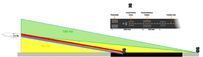
- Localizer
- Glideslope
- Approach lights
- Marker beacon
- Localizer
- Provides lateral guidance
- Placed on the departure end of the runway
- More sensitive on the back course
- The signal represents only one magnetic course to the runway
- Regardless of what course you select, the CDI will indicate the same off course
- This can be compared to GPS navigation and cid indication
- Always set to the approach course for easier guidance
- You will get reverse sensing if you set and HSI/VOR to the inbound localizer back course
- Always set to the inbound front course
- Full deflection is 2.5º
- 4x more accurate than a VOR(10º full deflection)
- Also more sensitive CDI
- Signal is provided up to 4500 feet
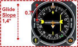
- Glide slope
- When you set the LOC frequency you automatically get the glide slope
- 0.7º full deflection
- Usually works up to 10 NM and usually a 3º glide slope, but can be different, depends on terrain
- Marker beacons
- Used to help you ID a position on the approach
- Usually only two marker beacon associated with a normal ILS.
- Outer marker (FAF)
- Middle marker - DA
- Inner marker
- Back course marker
- When you fly over a marker, you will receive a light and sound
- Compass locator
- low power NBD transmitter installed together with the OM and MM on some ILS approaches
- Inoperative components
- The lowest landing minimums are authorized only when all components are operational
- When on component is inop. You must increase altitude and/or visibility
- More than one component is inop. Apply the greatest increase required by any single inop component
- When glide slope becomes inop. Use LOC minimums
- Inop. component table in TPP’s
- Flying the ILS
- ID the ILS/LOC frequency
- Intercept the localizer
- Maintain localizer and glideslope centered
- Straight-in (NoPT) ILS approach
- ILS approach with course reversal
- Fly procedure turn/hold, then intercept the LOC
- ILS/DME approach
- Radar vectors to ILS final approach course
- ATC will vector you to the FAF
- ILS approaches to parallel runways
- Simultaneous converging instrument approach
- Localizer approach
- LDA - localizer type directional AID
- More precise than SDF
- If not aligned with the runway, may still provide straight in if less than 30º off
- Limited approaches have glide slope
- SDF - simplified directional facility
- Localizer type, may be wider(16 or 12 degrees) - less precise
- May or may not be aligned with runway
- No glide slope
- Localizer back course approach .


No comments:
Post a Comment