- Flight instrument systems
- FAA instrument requirements
- FAR 91.205
- VFR instruments + IFR instruments
- IFR - GRABCARD
- Generator/alternator
- Radio
- Altimeter
- Ball
- Clock
- Attitude indicator
- Rate of turn coordinator
- Directional gyro
- Pilot's Operating Handbook (POH)
- Gyroscope principals
- Gyroscopic precession
- A force applied to a gyro will react 90º later in the direction of rotation
- Used by turn coordinator/indicator
- Rigidity in space
- Means that once the gyro is spinning, it tends to remain in a fixed position
- Resists external forces applied to it
- Used by DG and AI
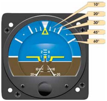
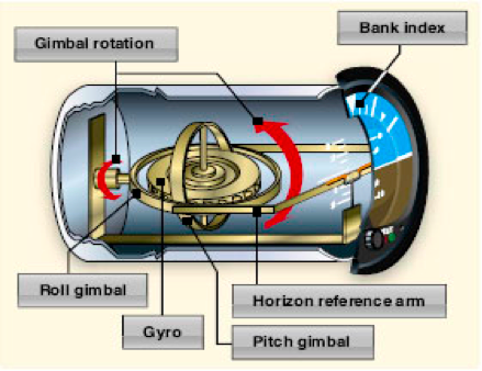
- Attitude indicator
- How it works
- Mounted on a double gimbal to sense pitch and roll
- Horizontal gyro, vertical axis
- Vacuum or electrical
- Errors
- Instrument tumbling/caging
- Exceeding pitch(60º) /roll (100º) limit, the gyro housing will contact the gimbals
- Maneuver errors
- Might get slight nose up/down when rapid acceleration/deceleration
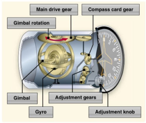
- Heading indicator/ Directional gyro
- How it works
- Uses rigidity in space
- Mounted in a double gimbal
- Spin axis horizontal, gyro vertical
- No compass errors
- Vacuum or electrical
- Errors
- Friction - earth rotates 15º every hour
- Must be set to agree with magnetic compass
- If fluxgate present
- Slave mode
- Aligns constantly to magnetic north
- Electric coils sense the direction by strength of current through them
- Does not need to be set manually every 15 minutes
- Turn indicator/coordinator
- How they work
- Usually electrical
- Uses precession
- Mounted in a single gimbal
- Horizontal axis, vertical gyro
- Turn indicator provides you with rate of turn
- Turn coordinator provides you with rate of turn and rate of roll
- Tilted 30º


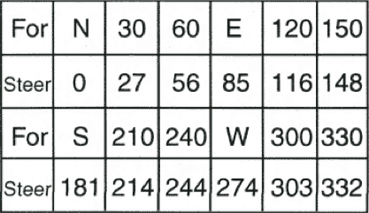
Magnetic compass
- Function
- Self contained
- Helicopter rotates around the compass card
- Magnetic fields of the earth
- The earth is a huge magnet surrounded by a magnetic field made up of lines of flux
- These lines leave magnetic north pole and reenter the south pole
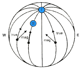
- Variation
- Angle between magnetic north and true north
- Deviation
- Compass errors caused by magnetic disturbances from electrical and metal components in the aircraft
- Magnets installed in housing to compensate for the error
- Correction is placarded on the compass
- Oscillation
- Erratic movements of the compass card
- Turbulence , control inputs
- Magnetic dip
- Tendency of the north seeking needle to deflect downward as it approaches the north pole
- Flux is Perpendicular at the magnetic north pole
- Strong deflection
- Flux is parallel at the equator
- No dip error
- Dip compensating weight at the “south end


- Dip errors
- Acceleration / deceleration errors
- Because of the weight that compensates for magnetic dip
- Most noticeable on easterly or westerly headings
- Non at north or south headings
- ANDS
- accelerate north/ decelerate south
- Turn errors
- Most noticeable when turning to/from a north or south heading, none at east/west
- UNOS
- Undershoot north, overshoot south
- When on a south heading and turning north, needle leads


Pitot-static instruments
- Pitot static system
- Pitot tube
- Dynamic pressure enters (ram air)
- Drain hole
- Some aircraft's have pitot heat
- Used by airspeed indicator
- Static port
- Measures static pressure
- Used by ASI, VSI, and ALT
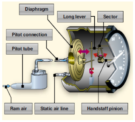
- Airspeed indicator
- Function
- Indicates the speed of the aircraft through the air
- Compares dynamic pressure with static pressure
- The greater the difference, the greater the speed
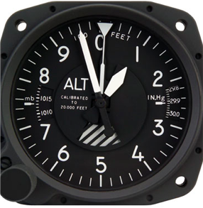
- Altimeter- +/-75 error permitted
- Function
- Measures the difference between static pressure and altimeter setting
- Static port connected to the housing
- Wafer has set pressure
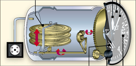
- Vertical speed indicator
- Function
- Displays rate of climb/ descent
- Measures how fast the static pressure increases and decreases
- Static pressure enters diaphragm which instantly compresses/ decompresses
- Static pressure also enters VSI housing through calibrated leak
- ICING
- Pitot tube ice
- Only affects the airspeed indicator
- Pitot + drain clogged = ASI works as altimeter
- Higher altitude = higher airspeed
- Pitot tube ice, drain cleared
- Drain hole lets the pressure out, airspeed drops to zero
- Static port ice
- Affects ASI, ALT, VSI
- ASI
- Works normal at altitude it froze at
- Higher airspeed at lower altitude, lower airspeed at higher altitude
- ALT
- Freezes at current altitude
- VSI
- Shows zero, senses no difference in pressure
- Alternate static source
- Break the VSI glass
- ASI and ALT will show higher than normal
.


No comments:
Post a Comment